Determination of the Moment of Inertia
of a Flywheel about its Axis of Rotation
A polished interactive lab workspace covering the theory, apparatus, procedure, simulation, observations, and result analysis for this rotational dynamics experiment.
Objective
Section 01Aim
Determination of the moment of inertia of a flywheel about its axis of rotation.
Learning Objectives
After completing this experiment, students will be able to:
- Understand the concept of moment of inertia as the rotational analogue of mass.
- Explain how a falling mass causes a flywheel to rotate and gain rotational kinetic energy.
- Measure the dimensions and angular motion parameters needed for the flywheel experiment.
- Determine the time required for a known number of revolutions of the flywheel.
- Apply the energy and kinematics relations to calculate the moment of inertia of the flywheel.
- Analyze the effect of mass, radius, and angular speed on rotational inertia.
- Identify experimental errors arising from friction, timing, and string winding.
- Relate the flywheel experiment to energy storage, mechanical systems, and rotating machinery.
After completing this virtual experiment, learners will be able to:
- Understand the concept of moment of inertia and its dependence on mass distribution.
- Observe how potential energy lost by a falling mass converts into rotational kinetic energy of the flywheel.
- Use the interactive simulation to vary mass, radius, and timing parameters.
- Analyze the relationship between falling mass and rotational motion.
- Determine the flywheel moment of inertia from simulated measurements using the appropriate formula.
- Interpret observations through tables, graphs, and computed values generated during the simulation.
- Evaluate how different experimental conditions influence the calculated inertia.
- Connect the flywheel experiment to real-life engineering applications involving energy storage and rotational dynamics.
Theory
Section 021. Definition and Fundamental Concept
The moment of inertia of a body about a given axis measures its resistance to a change in rotational motion. It is the rotational analogue of mass in translational motion.
For a system of discrete particles and for a continuous body, respectively:
I = ∫ r2 dm
The SI unit of moment of inertia is kg·m2. Mass farther from the axis contributes more strongly because of the square of its distance.
2. Construction of the Flywheel
The flywheel is treated as three coaxial parts of uniform density ρ:
- a cylindrical axle of radius r1 and length l;
- an inner annular portion with radii r1, r2 and thickness t1;
- an outer annular rim with radii r2, r3 and thickness t2.
The total moment of inertia is found by adding the moments of inertia of these components.
3. Geometrical Moment of Inertia
For the cylindrical axle, m1 = ρπr12l and:
For an annular cylinder, I = 1⁄2m(a2 + b2). Therefore:
I3 = 1⁄2πρt2(r34 − r24)
Hence, the theoretical moment of inertia of the complete flywheel is:
4. Experimental Arrangement
The flywheel is mounted horizontally on a fixed axle. A light string is wound around the axle and attached to a slotted mass m. If the string is wound through n1 turns and the axle radius is r, the mass descends through:
The lost gravitational potential energy becomes rotational kinetic energy of the flywheel, translational kinetic energy of the falling mass, and energy dissipated by friction.
5. Energy Relations
Just before the string detaches, let the angular velocity be ω. Since the string does not slip, v = rω. Thus:
ER = 1⁄2Iω2
ET = 1⁄2mv2 = 1⁄2mr2ω2
If WF is the work done against friction per revolution, the energy equation while the string is wound is:
6. Frictional Energy Loss
After detachment, the flywheel makes n2 further revolutions in time t before stopping. Its rotational kinetic energy is completely dissipated by friction:
WF = Iω2 / (2n2) (2)
Substituting (2) in (1) and simplifying gives the experimental expression:
7. Angular Velocity at Detachment
Assuming approximately uniform angular retardation after detachment, the average angular velocity is ω/2. The angular displacement is 2πn2, so:
ω = 4πn2/t (4)
Equation (4) supplies the angular velocity required in equation (3).
8. Symbols and Important Results
| Symbol | Meaning | SI unit |
|---|---|---|
| I | Moment of inertia of flywheel | kg·m2 |
| m | Falling/slotted mass | kg |
| r | Radius of axle | m |
| n1, n2 | Turns before and revolutions after detachment | dimensionless |
| t | Time taken to stop after detachment | s |
| ω | Angular velocity at detachment | rad·s−1 |
| WF | Work done against friction per revolution | J |
| ρ | Density of flywheel material | kg·m−3 |
Use equation (3) with equation (4) to determine the experimental moment of inertia. This result includes the translational kinetic energy of the falling mass and the energy lost against friction.
Apparatus Required
Section 03Apparatus
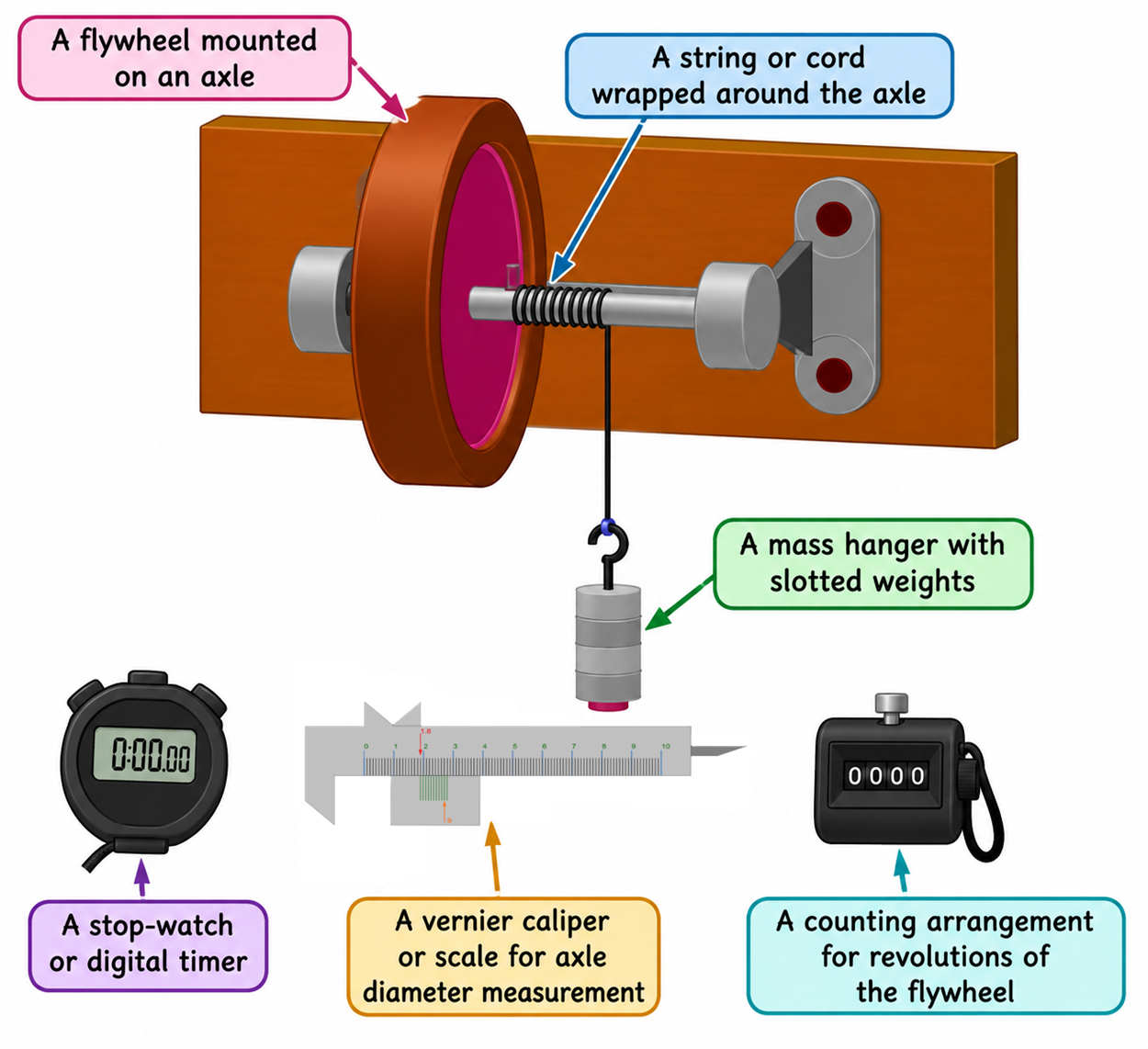
- A flywheel mounted on an axle
- A string or cord wrapped around the axle
- A mass hanger with slotted weights
- A stop-watch or digital timer
- A vernier caliper or scale for axle diameter measurement
- A counting arrangement for revolutions of the flywheel
Procedure
Section 04Procedure (Real Experiment)
- Measure the diameter of the axle using a Vernier caliper. Calculate the radius r of the axle as half of the measured diameter: r = d⁄2.
- Ensure that the flywheel assembly is mounted horizontally and is properly supported by the ball bearings. Lubricate the bearings adequately so that the flywheel rotates freely with minimum friction.
- Take a string of suitable length and attach one end securely to the peg on the axle. Wind the string uniformly around the axle for a suitable number of turns, n1. The length of the string should be sufficient for it to unwind completely and detach from the peg before the attached mass reaches the floor.
- Hold the flywheel stationary and attach the other end of the string to a mass hanger carrying a suitable slotted mass m.
- Measure and record the height of fall of the mass. Release the flywheel gently, allowing the mass to fall freely and the string to unwind from the axle.
- When the string completely detaches from the peg, start the stopwatch immediately and count the number of rotations, n2, made by the flywheel until it comes to rest. Stop the stopwatch when the flywheel has completely stopped and record the time t.
- Record the observations for each trial in a suitable table, including the mass m, number of initial windings n1, height of fall h = 2πrn1, number of rotations after detachment n2, time t, and the calculated mass moment of inertia I.
- Repeat the experiment for several trials, using the same or different masses and/or heights of fall. Multiple observations help improve the reliability of the results and reduce the effect of experimental errors.
- Calculate the moment of inertia I of the flywheel for each trial using the derived experimental formula. Finally, determine the mean value of I from all trials and compare it with the theoretical value to assess the accuracy of the experiment.
Procedure (Virtual Experiment)
Open the Simulation section of the experiment and switch to full-screen mode for better visibility.
1. Measurement of the Radius of the Axle of the Flywheel
- Click on “Simulation-1: Measurement of Radius (r) of Axle.” A virtual Vernier caliper and the cross-section of the flywheel axle will be displayed.
- Determine the least count and zero error of the Vernier caliper before taking measurements.
- Open the jaws of the Vernier caliper by dragging the Vernier scale.
- Drag the cross-section of the axle into the space between the jaws and release it.
- Close the jaws gently until they just touch the axle cross-section. Record the Vernier caliper reading.
- Repeat the measurement three to four times to improve reliability.
- Enter all observations in the Observation Table: Measurement of Radius (r) of Axle.
- Apply the appropriate zero-error correction to each observation and calculate the mean radius r of the axle.
2. Determination of the Moment of Inertia of the Flywheel
- Click on “Simulation-2: Experiment on Flywheel.”
- Reset the stopwatch using the reset button located at the top-right of the stopwatch display.
- Set the flywheel dimensions using the available controls and note the theoretical value of MI of the flywheel.
- Select a suitable mass m for the mass hanger using the Load Slider.
- Wind the string uniformly around the axle for a suitable number of turns, n1, using the Number of Turns (n1) Slider.
- Start the experiment by clicking the Play button on the stopwatch to release the mass from rest.
- When the string detaches from the axle peg, start the stopwatch immediately. At the same time, count the number of rotations n2 made by the flywheel after the string detaches and until the flywheel comes to rest. Verify the rotation count using the data provided in the simulation.
- Stop the stopwatch as soon as the flywheel comes completely to rest and record the time t.
- Enter the experimental data in Observation Table 2, including:
- Mass of the load, m
- Number of initial windings, n1
- Height of fall, h = 2πrn1
- Number of rotations after detachment, n2
- Time of rotation, t
- Calculate the moment of inertia I of the flywheel for each trial using the derived experimental formula.
- Repeat the procedure for several trials to obtain reliable results. Calculate the mean value of the moment of inertia and compare it with the theoretical value to evaluate the accuracy of the experiment.
Simulation
SimulationObservation Table
Section 06Table 1: Radius of Axle (r)
Table 2: Revolutions and Angular Motion
Result and Analysis
Section 07Result summary
Use the measured values to calculate the moment of inertia of the flywheel about its axis of rotation.
Calculation on freehandTool
Moment of Inertia of a Flywheel
Select the most appropriate answer for each question.